Introduction
A computer system is a machine that accepts the data, processes it and gives a meaningful result to the user. In simpler words, A computer system is a machine that simplifies tasks. Computer architecture is a detailed description about how a set of software and hardware technologies interact to form a computer system. This system consists of different components such as Input Unit, Output Unit, Memory Unit, Arithmetic Logic Unit, Control Unit.

Now, let us get familiar with some of the terms of computer architecture and their uses.
Register – Register is a computer memory that accepts, stores, and transfers data and instructions that are being used immediately by the CPU.
Most commonly used registers include:
- Processor Register – A quickly accessible location available to computer’s central processing unit .
- Memory Address Register – Holds the address of the memory unit.
- Instruction Register – Stores the instruction fetched from the main memory.
- Status Register – Stores the status of the instruction that is being executed.
- Program Counter – contains the address of the instruction being executed at the current time.
Micro operation – Operations executed on data stored in one or more registers.
Instruction Cycle
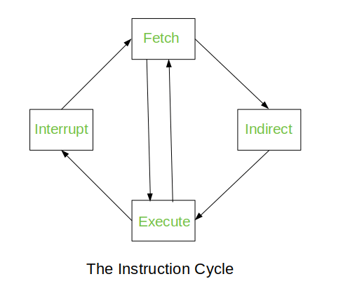
Program residing in the memory unit of a computer consists of a sequence of instructions. These instructions are executed by the processor by going through a cycle for each instruction called as the Instruction cycle. They are also called as the fetch – execute cycle because an instruction cycle,
- Fetch an instruction from the memory
- Decode the instruction.
- Read the effective address from the memory if the instruction has an indirect address.
- Execute the instruction.
Once all these four steps have been performed, the control is sent back to step 1. This process continues until an interrupt occurs.
- Fetch – Initially the sequence counter is initialized to zero. In the first clock cycle, as the first instruction has to be executed its address is stored in the program counter and from the PC the address is then copied to the Address Register.
In the next clock cycle, The the instruction from the Memory of the Address Register is stored in the Instruction Register and the Program Counter points to the next instruction to be executed.
- Decode – In this phase the decoding of the operation is done by using the instruction format.
- Decision – The instruction has three types ( Memory reference, Register reference, I/O reference. Here in the decision phase, the type of the instruction has to be decided. It is decided by D7. The opcode has vales from 000(D0) – 111 (D7). If the value of D7 is 1 i.e 111 the type of the instruction is either Register reference or I/O reference. Now we further check for the value of the fifteenth bit(Instruction bit or I). If the value I is 1 then the instruction is of the type, I/O reference and if I is 0 then the instruction is of the type, Register reference. Then the instructions will be executed accordingly.
D7 has any other value except 1 then the instruction is of the type, Memory reference. Here if the value I is 1 then the instruction is direct and if I is 0 then the instruction is indirect.
- Execute – If the instruction is of the type I/O reference or Register reference or the direct Memory reference then the instruction is executed. But if the instruction is indirect memory reference type then the effective address is stored in the address register and then the instruction is executed.
After the execution the sequence counter is set to 0.
Memory Reference Instruction
These instructions refer to memory address as an operand. The other operand is always accumulator. Specifies 12-bit address, 3-bit opcode (other than 111) and 1-bit addressing mode for direct and indirect addressing.
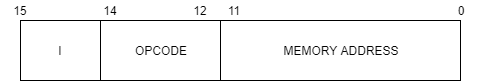
In the control unit of the computer, the 12th, 13th and the 14th bit instructions enter a 3*3 decoder which produces D0 to D7 outputs which are nothing but different operational codes. Here if the value of D7 was anything except 1 then the type of instruction was called as the memory reference instruction. Further the value of the 15th bit is 1 the the instruction is said to be direct and if the value of I is 0 the the instruction is said to be indirect.
The values from D0 to D7 are for different operation codes and they perform seven different operations.
- D0 (AND to AC) – This is the first operational code and this for AND to Accumulator. Here an AND operation is performed between the data of the effective address and the bits of the accumulator. The contents present in the memory of the Address Register(AR) is copied into the Data Register(DR) and then the AND operation is performed between the bits of the accumulator and the data register which has the memory of the AR. Once this is done the Sequence Counter (SC) is set to zero.
- D1 (ADD to AC) – Here ADD operation is performed between the bits of the accumulator and the DR and the SC is set to 0. If there is a carry after the ADD operation then it is stored in the extended accumulator.
- D2 (LDA – Load Accumulator) – Here the the value of the DR is stored in the accumulator.
- D3 (STA – Store Accumulator) – The value of the accumulator is stored in a particular MAR.
- D4 (BUN – Branch Unconditionally) – The effective address of the instruction that is to be executed next is copied to the program counter. It allows the programmer to specify an instruction out of sequence and we say that the program jumps(branches) unconditionally.
- D5 (BSA – Branch & Save return Address) – Useful for branching to a portion of the program called the subroutine or procedure. When executed, it stores the value of the next instruction sequence into the memory location specified by the effective address.
- D6 (ISZ – Increment & Skip if Zero) – Here the word that is specified by the effective address is incremented and check if that incremented value is 0. If the incremented value is 0 then the PC value is incremented by 1 else not. Basically, The contents of the MAR are transferred to DR, then DR is increment by 1. If the incremented DR is 0 the the PC value is incremented by 1.
I/O and Interrupt
An input device sends information to a computer system for processing, and an output device reproduces or displays the results of that processing. Input devices only allow for input of data to a computer and output devices only receive the output of data from another device. Instruction and data stored in the memory must come from some input device. Computational results must be transmitted to the user through some output device.

Here in above image, INPR is the Input Register, OUTR is the Output Register, AC is the accumulator, FGI and FGO are the control flags, where one is the input flag and the other is the output flag. Here the communication between the input and the output devices through the interfaces is shown. As soon a key is pressed on the keyboard the information is stored in the input register through the transmitter interface. Initially the value of the input flag is set to 0. As soon the INPR receives the information the value of the FGI is set to 1. Once the value of FGI is set to 1, no other information is sent to the INPR by the input devices . Then the information is is passed on to the accumulator and once the information is passed to the accumulator the value of the FGI is set to 0 again. Now the information was which in the accumulator is sent to the OUTR (note that the value of the FGO was already set) and as soon as the information is received by the OUTR the FGO is set to 0. Then information passed through the receiver interface and then sent to the output device.
Interrupt is similar to a subroutine. An interrupt occurs when there is a transfer of program control from the currently running program to a service program as a request of the external or internal generated request. An interrupt is generally initiated by the internal or external signal rather from execution of instructions. The ISR (Interrupt Service Routine) manages the interrupt and the PSW (Program Status Word) which stores the status of all the bit conditions of the CPU manages the priorities while running the program.
The interrupts are of 3 types.
- External – Interrupt caused by the the hardware devices.
- Internal – Interrupt occurred by the currently running program.
- Software – External and internal interrupts are initialized the computer hardware and the software interrupts are initialized by executing an instruction.
Interrupt Cycle
Reference:
- https://www.academia.edu/31003870/Computer_System_Architecture_3rd_Ed_by_M_Morris_Mano_text.pdf
- https://www.tutorialspoint.com/Computer-System-Architecture
- https://www.javatpoint.com/instruction-cycle
- https://www.geeksforgeeks.org/different-instruction-cycles/
- https://www.youtube.com/watch?v=PMSkW3Z8f4E
- https://www.youtube.com/watch?v=aZL4DsnLg_E
- https://www.youtube.com/watch?v=lxBfuyOagS8
